|
CROSSOVER THE CABS MEASUREMENTS CROSSOVER KIT
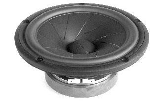
ScanSpeak driver data sheets: 18W/8531-G00 + 12M/4631-G00 + R2904/700000 or R2604/832000 |
|
CROSSOVER THE CABS MEASUREMENTS CROSSOVER KIT
ScanSpeak driver data sheets: 18W/8531-G00 + 12M/4631-G00 + R2904/700000 or R2604/832000 |
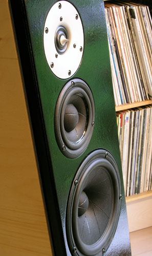
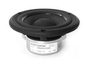
The sliced paper driver 18W/8531-G00 is one of the most potent 6-7" midbass I have ever experienced. It did great in the SP95 set-up. It did even better in the SP38 construction and here's the best I have ever heard from this driver and probably due to the cabinet made from curved and laminated side panels producing the most rigid enclosure I have tested. Un-coated paper cones
will always leave a fingerprint on the reproduced sound
and the sliced paper drivers are no exception from this
rule. Having a 6-7" un-treated paper cone handling a
very wide frequency range in a two-way construction is
tough. It helped a lot taking the first point of
crossover down to 1600 Hz by the D3806/8200 tweeter and
here we have the option 2 again from my thoughts about
various ways of designing 2- and 3-way speakers with
regard to the chosen points of crossover: After doing the 3½-way Zahra: http://www.troelsgravesen.dk/8543.htm, I was happy repeating this approach and in particular with drivers I knew from other constructions. I've made a crossover for a construction including the coated version of the 12M middriver (not published - and shall not) and it did very well despite having to mate two dedicated 8" bass drivers at around 450 Hz. Not my favourite set-up, but this was how the cards were played from the constructor. The construction shown here is the result of another DIY-service project and again the owner has allowed the publication of his construction. Thanks to Jesper. This time I was presented with the finished cabinets and only had to do the crossover. However, a "12M" project was definitely one of the things I would like to do and my own thinking about this small mid-driver was either a single 18W/8531-G00 bass driver + 12M + tweeter or a big 3-3½-way from two 18W/8531-G00 drivers. More on that one later. Getting the 7000 tweeter mating a 15M mid-driver wasn't successful in the wide baffle set-up, but you can never tell how a driver will perform in another set-up. Maybe the 12M would be the ideal partner for the much too expensive 7000 tweeter. Well, the other drivers are ripoff too, but not much we can do about it unless we form a Sliced Paper Club and buy 500 pcs each.
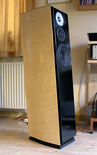
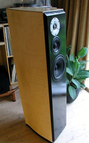
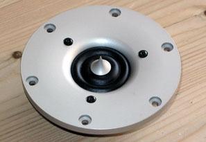
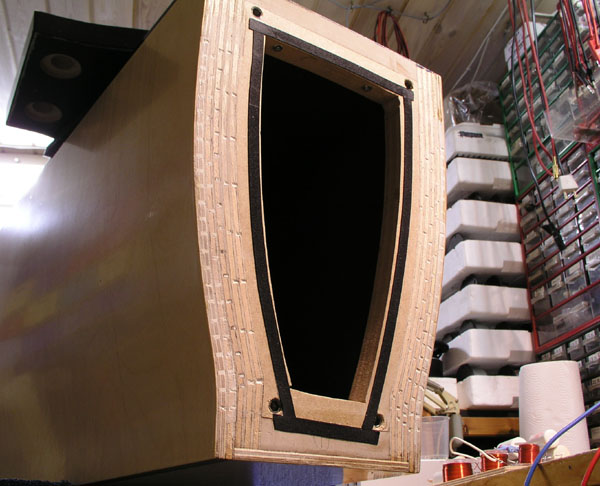
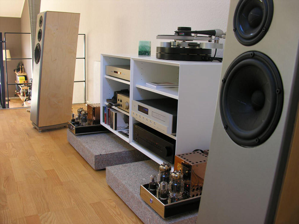
The cabinets are made around the SP38 front baffle layout. The front panel size, tilt and placement of drivers are almost identical to the SP38 and you can use this cabinet by adding a 1.5 litre mid-driver enclosure. Cabinets made
from multiple layers of plywood What Jesper has produced here is probably the most rigid cabinet I have ever seen - and felt. The knockletest is like hitting a solid log of hardwood. The side panels are made from 4 layers of plywood with an overall thickness of 30 mm. The front panel has a subpanel, thus reaching a thickness of 45 mm. This takes some serious chamfering of driver holes to make the drivers breathe. Don't report back it sounds crap if you have stuck the 12M into a tube! The cabinet volume is 32 litres minus mid-driver enclosure and bitumen pads (4 mm). The vent tuning is 33 Hz (65 (ID) x 150 mm vent).
Cabinet details:
Cabinet damping: Please read here
general advise on damping of a 24-32 litre floorstander: Again the drivers were linearised by passive components and a 3-way electronic crossover was attached and adjusted to produce a reasonably linear frequency response. The point of crossover between bass and mid was varied from 350 to 1000 Hz and from 2000-5000 Hz between mid and tweeter. This was done while listening to various kinds of music and vocals to possibly render the best points of crossover. Taking the 12M down to 400 Hz made the speaker sound rather thinnish with lack of volume to particularly vocals and somewhere between 600 and 1000 Hz appeared to make a good balance between bass and mid. The point of crossover between mid and tweeter was somewhat more difficult as the differences weren't so clear. I have a CD with a particular sibilant female vocal and this recording suggested a crossover in the 3.5-4 kHz region to work the best. Next thing to do was
creating the frequency/phase and impedance data files
from all drivers and start LspCAD simulations to see
whether a passive crossover could be constructed with the
chosen points of crossover in mind - and still rendering
a reasonably flat FR profile. Preferably with the
simplest possible crossover. The version 1 crossover below may actually be the 5th version of the first crossover, but I'll spare you all the details. Playing around with the LspCAD I also tried a 1st order filter, something I mostly stay far away from. The huge overlap between drivers creates - to my ears - a lot of intermodulation distortion unless played a very low volume, but in this case both FR and phase turned out so nice that I put together a crossover to make an AB test with the version 1 crossover seen below. Making a 1st order network really takes quite a few components, almost as many as the 2nd order filter. The drivers' impedances has to be linearised, e.g. the tweeter resonance peak at 500 Hz has to be removed as the bass and tweeter cross only 15 dB down around 1800 Hz. The mid has to attenuated considerably and is 4 dB below summed response due to the huge overlap of drivers. Anyway, despite having a similar amplitude profile the speakers sounded very different and what made the biggest difference was the sibilance from the 1st order filter. Some more modelling and crossover tweaking was not enough to remove this phenomenon and the 1st order filter was discarded. I have with interest read the recent review of the Audio Physic Caldera loudspeaker in Stereophile Dec. 2005. The 7000 tweeter is used here although in a very unusual fashion as the faceplate is removed and the tweeter is hung in three wires in front of the main mid-driver to resemble a coax driver. Michael Fremer had major trouble with this speaker and from John Atkinson's measurements it seems clear that the 7000 tweeter has an average 3-4 dB higher amplitude compared to the midband. Due to a narrow dip above 2 kHz there's a 10 dB jump from 2.3 kHz to 4 kHz! It sounded so bad that a new pair of speakers were required and this time the tweeter level appeared to have been attenuated further, although only approx. 1 dB. The frequency response is nice and flat from 100 to 2000 Hz and the rest is still some 3-4 dB above average. I really wonder what the 7000 tweeter sounds like from this set-up...
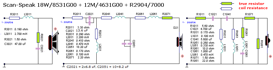
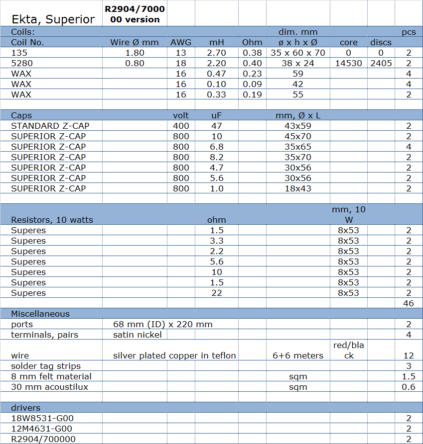
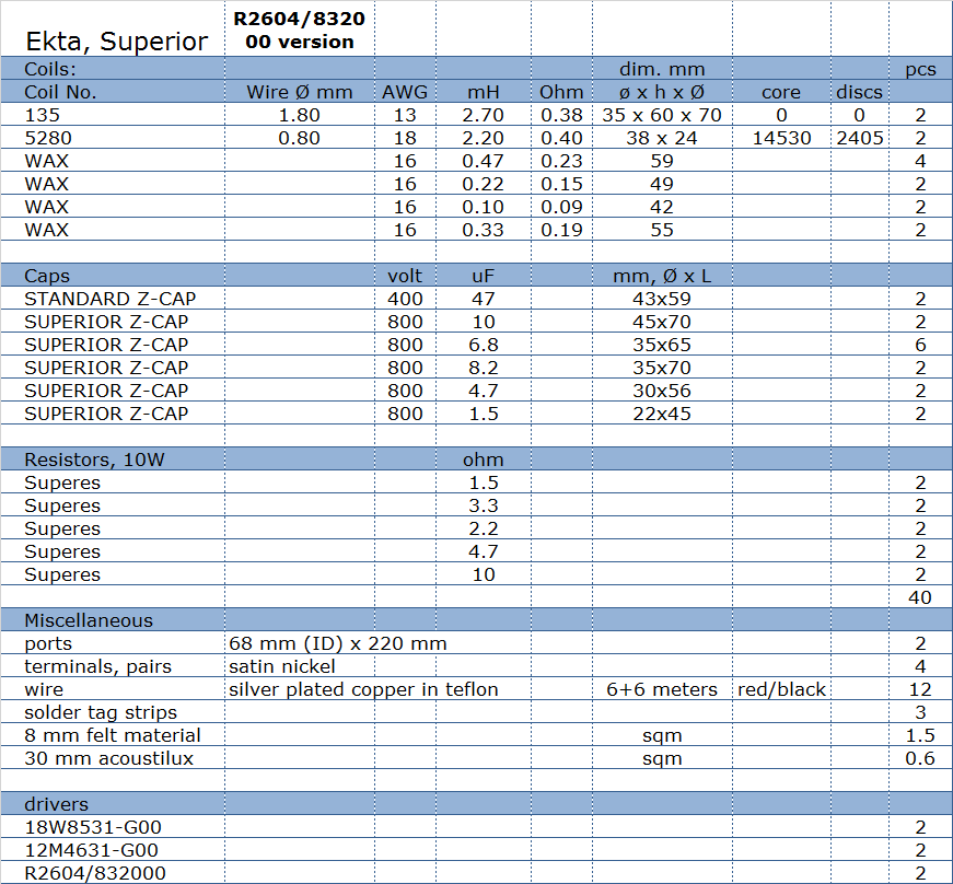
Crossover components
Complete crossover kit with/without drivers available from Jantzen Audio: contact@jantzen-audio.com Download Kit Sales Presentations here.
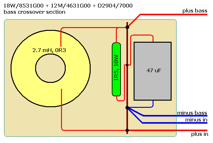
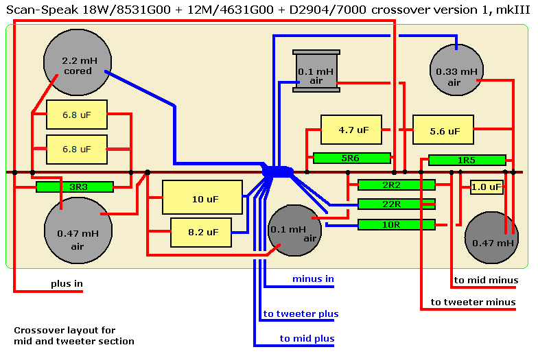
Crossover layout
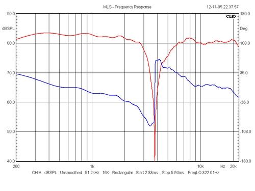
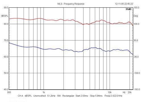
Left: Phase tracking between mid and
tweeter. Blue = minimum phase. As can be seen there's an
almost 180 deg. phaseshift at 3800 Hz when mid and
tweeter has opposite polarity.
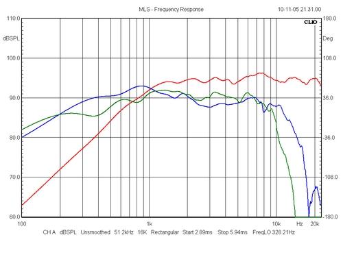
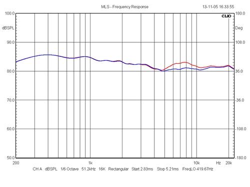
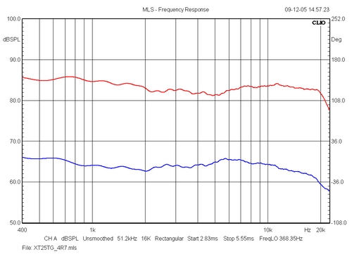
Left: Preliminary frequency response of
"final" crossover. Note the is a bump at 7.5
kHz from the 7000 tweeter. Initially I thought this was
no big deal, but the tweeter persistently kept reminding
me of its presence going trough a number of tracks.
Hmm... if you can "hear" the tweeter as such,
there's a problem.
I'm sure there will be questions about the 7000 tweeter. Please another one! The price of the 7000 is a killer and I fully agree. The price is way too much. It's a fine tweeter, but it's not that great. To be honest, I'll bet that R2604/832000 at one-tenth the price of the 7000 will do as well as the 7000 tweeter as it only has to handle down to 3800 Hz. ScanSpeak R2604/832000 version I have tried modelling ScanSpeak R2604/832000 tweeter. Much easier compared to the
troublesome 7000 tweeter. The changes are:
Tweeter section:
|